Stepper Motor Step Angle and Calculation Formula: A Complete Technical Guide
The Stepper Motor Step Angle and Calculation Formula is one of the most important concepts in motion-control engineering. Step angle defines the minimum mechanical movement a stepper motor can achieve when the excitation of the stator winding changes once. Because stepper motors are widely used in automation, CNC machinery, 3D printers, semiconductor equipment, and precision positioning systems, understanding step angle and its calculation is essential for selecting the correct motor for industrial applications.
1. What Is Step Angle in a Stepper Motor?
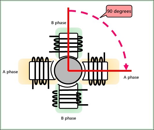
The step angle is the fixed angular displacement the rotor moves with every excitation change. When the stator winding switches current between phases, magnetic fields shift position, pulling the permanent-magnet or hybrid rotor into alignment. This controlled and repeatable movement defines the fundamental resolution of the motor.
A smaller step angle means smoother motion, lower vibration, and higher positioning accuracy. For this reason, step angle is one of the first parameters engineers check when selecting a motor for their system.
2. Basic Step Angle Calculation Formula
The simplest and most widely used formula for calculating the step angle is:
Step Angle = 360° ÷ N
Here, N represents the total number of magnetic poles across all phases. It is calculated as:
N = NPH × PH
NPH = number of magnetic poles per phase
PH = number of stator phases
N = total magnetic poles
For example:
A 2-phase, 4-pole stepper motor → N = 2 × 4 = 8
Step angle = 360° ÷ 8 = 45°
This formula shows how increasing the number of poles or phases reduces the step angle and increases resolution.
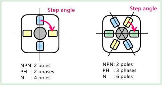
Left side: Two-phase / Four-pole Right side: Three-phase / Six-pole
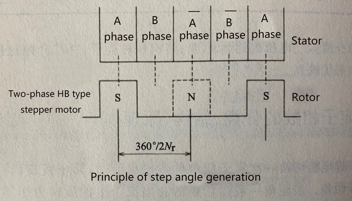
3. Step Angle in Permanent-Magnet and Hybrid Stepper Motors
Most industrial motors today, including those sold in the HDBMOTOR product line, use permanent-magnet (PM) or hybrid rotors due to their high efficiency and precision.
For PM stepper motors, another commonly used formula is:
Step Angle = 180° ÷ (P × Nr)
P = number of stator phases
Nr = number of rotor pole pairs
The physical meaning is simple:
A full rotation is 360°. Dividing by 2Nr gives the mechanical angle per rotor pole. Dividing that by the number of phases gives the step angle.
This formula explains why increasing rotor pole pairs leads to smaller step angles and improved resolution.
4. Common Industrial Step Angles and Their Applications
1.8° Step Angle (200 steps per revolution)
• Most common in automation
• Ideal for CNC, 3D printers, XY tables
• Balanced torque and resolution
0.9° Step Angle (400 steps per revolution)
• Higher precision
• Reduced vibration and smoother micro-positioning
• Suitable for semiconductor equipment, inspection systems, and precision instruments
Microstepping drivers can further subdivide these angles, improving smoothness at the cost of torque.
5. Why Step Angle Matters in Real Industrial Applications
Understanding the Stepper Motor Step Angle and Calculation Formula helps engineers:
• Determine achievable positioning accuracy
• Select a motor compatible with mechanical resolution requirements
• Match motor performance with load inertia
• Improve smoothness and noise performance
• Ensure compatibility with controller step frequency
For example, if your application requires 0.01 mm linear positioning accuracy, the step angle and screw pitch must be calculated together to ensure the system meets the requirement.
6. Improving Step Resolution: Practical Engineering Limitations
To achieve a smaller step angle, two strategies exist:
Increase the number of stator phases
Increase the number of rotor pole pairs
However, rotor pole count is limited by manufacturing constraints. Therefore, high-precision motors often combine optimized rotor design with multi-phase stator systems and microstepping.
Conclusion
The Stepper Motor Step Angle and Calculation Formula is essential knowledge for engineers designing motion-control systems. Step angle determines resolution, affects vibration, and directly impacts positioning accuracy. Whether you work with 1.8° motors, 0.9° motors, or custom high-resolution types, understanding step angle formulas helps ensure correct motor selection for automation, robotics, CNC machines, and precision equipment.
If you need help choosing the right stepper motor, HDBMOTOR can provide selection advice and customize motors based on torque, speed, load, and resolution requirements.