
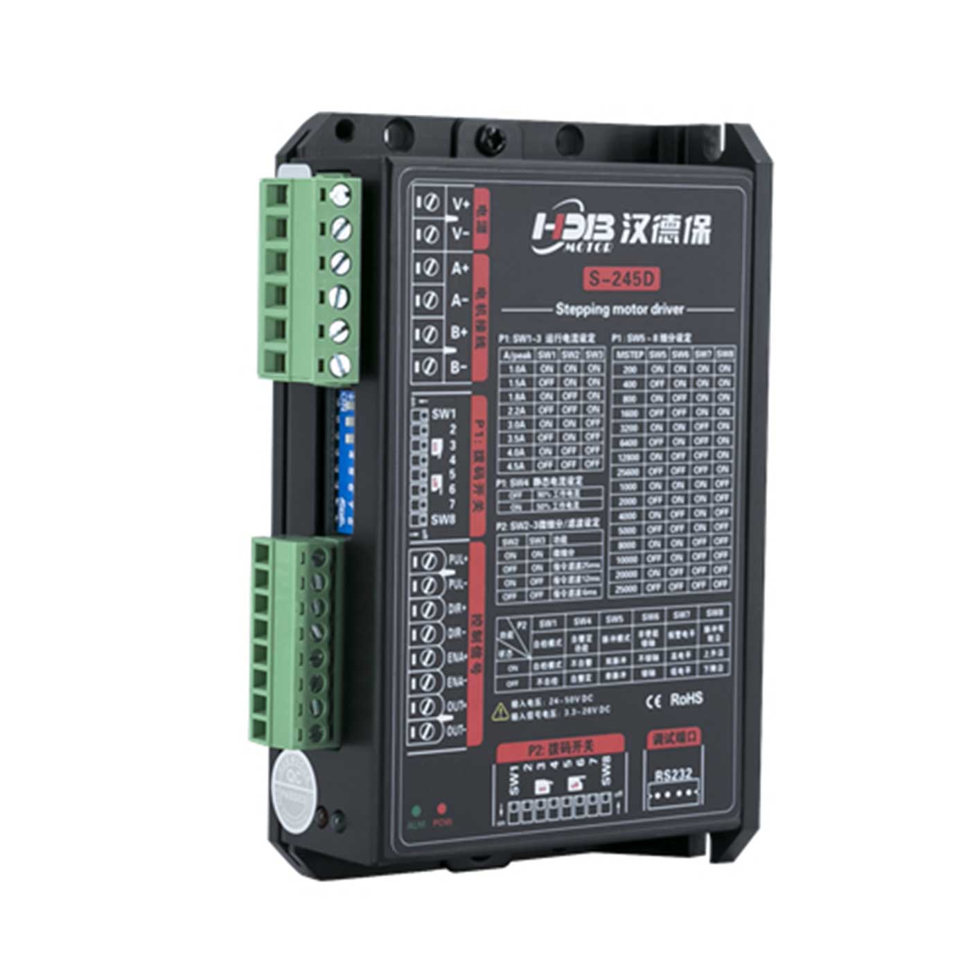
Main Control Chip: Uses the latest 32-bit DSP chip dedicated to stepper motor control.
Voltage and Current:
Input voltage: 24~50 VDC
Output current: 1.0A~4.5A (peak)
Microstepping Settings: 16-level microstepping selectable (200~25600 pulses/revolution).
Response Frequency: Pulse response frequency up to 500 KHz.
Signal Voltage: Pulse/Direction/Enable signals compatible with 5V~24VDC, no additional current-limiting resistor required.
Control Modes: Single pulse (Pulse + Direction), Dual pulse (CW/CCW).
Product Self-Test: DIP switch setting enables self-test where the motor runs forward and backward repeatedly at 30 RPM.
Resonance Suppression: Automatically calculates resonance points to suppress medium and low-frequency vibrations.
Torque Smoothing: Analyzes low-speed torque ripple and cancels corresponding harmonic components to achieve smooth low-speed motion.
Signal Smoothing: Dynamic filtering of speed and direction signals to ensure more stable system performance.
Current Control: PID current control for high-speed, high-torque output with low noise, low vibration, and low heat generation.
System Self-Testing: Automatically detects and matches motor parameters, optimizes motor input current in real time according to load conditions.
Microstep Interpolation: Reduces vibration during operation and improves running smoothness.
Standby Current: Set by DIP switch, standby current is 50% or 90% of working current.
Compatible Motors:
The S-245D two-phase stepper driver is suitable for 4, 6, or 8-wire two-phase stepper motors with outer diameters of 57/60 mm and rated current between 1.0A and 4.5A.
Generally, stepper motor selection mainly depends on motor torque and rated current. The torque size depends on the motor size — larger motors have greater torque. The current size depends mainly on inductance — motors with smaller inductance have larger current and perform better at high speeds.
Application Fields:
Widely used in automation equipment across machinery, electronics, precision instruments, metering devices, and medical equipment. For example: linear slides, electronic devices, optical instruments, laser equipment, security devices, welding equipment, dispensing equipment, automatic assembly equipment, etc. Especially ideal for user scenarios demanding low noise and medium-to-high speed operation.
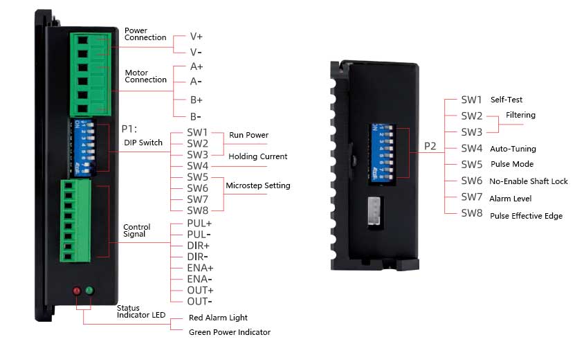
1) Motor and Power Input Terminals
| Terminal Number | Symbol | Name | Description |
|---|---|---|---|
| 1 | V+ | DC Power Input | +12VDC~ +48VDC |
| 2 | V- | Power Ground | 0V |
| 3 | A+ | Phase A Motor Coil + | Swapping the wiring of the same phase coil can change the motor’s rotation direction. For example, swapping the connections of A+ and A-. |
| 4 | A- | Phase A Motor Coil - | |
| 5 | B+ | Phase B Motor Coil + | |
| 6 | B- | Phase B Motor Coil - |
2) Control Signal Terminals
| Terminal Number | Symbol | Name | Description |
|---|---|---|---|
| 1 | PUL+ | Pulse Input Positive Terminal | Compatible with 4.5V to 24VDC signals |
| 2 | PUL- | Pulse Input Negative Terminal | |
| 3 | DIR+ | Direction Input Positive Terminal | |
| 4 | DIR- | Direction Input Negative Terminal | |
| 5 | ENA+ | Enable Input Positive Terminal | OC output, by default outputs low level when a fault occurs (30VDC/100mA max). |
| 6 | ENA- | Enable Input Negative Terminal |
3) Status Indicators
The green LED is the power indicator. When the driver is powered on, this LED flashes; when the driver is powered off, this LED goes out.
The red LED is the fault indicator. When a fault occurs, this indicator LED flashes periodically; when the fault is cleared by the user, the red LED remains off. The number of red LED flashes represents different fault information, as shown in the table below:
●The red LED ●The green LED
| No. | LED Flash Pattern | Fault Description | Solution |
|---|---|---|---|
| 1 | ● Green LED steady | Driver not enabled | Provide enable signal to driver |
| 2 | ●● Green LED flashing | Driver operating normally | / |
| 3 | ●●●●● 3 red 2 green | Internal voltage error | Increase power supply capacity |
| 4 | ●●●●●4 red 1 green | Driver power input overvoltage | Reduce power supply voltage |
| 5 | ●●●●●●5 red 1 green | Driver overcurrent | Check for short circuit or phase error |
| 6 | ●●●●●●4 red 2 green | Driver power input undervoltage | Increase power supply voltage |
| 7 | ●●●●●●●6 red 1 green | Motor winding open circuit | Connect motor wiring properly |
When the driver encounters a fault, it will stop running and display the corresponding fault code. The user needs to power off and then power on again to clear the fault, or clear the fault via the ENA offline signal and then re-enable the driver. When a fault occurs, the driver saves the latest fault in the EEPROM in a queue format.